


Andreas Gruentzig performed the first coronary artery angioplasty in Zurich in 1977, using equipment constructed in his apartment. The basic equipment involved in performing percutaneous coronary interventions (PCI) – guiding catheters, guide wires and balloons – have undergone significant evolution since Greuntzig’s seminal procedure. This has resulted in marked improvements in both procedural success, as well as safety. In PCI, as with any procedure, the equipment is a critical procedural component. Overall, the majority of PCI equipment is effectively interchangeable. Despite this, the coronary interventionalist should possess a thorough working knowledge of the available equipment, and the ability to select specific equipment for a given case. The ability to precisely select equipment can result in the difference between a safe, elegant, short intervention and a prolonged and technically challenging one that may result in complications.
Guiding Catheters
Perhaps the most important decision point in any intervention after patient selection is selection of the guiding catheter. Guide catheters are required for all coronary interventions to provide access to the coronary ostium and support equipment delivery. The ideal guide provides stability for device advancement through the coronary anatomy, while minimising vessel trauma and allowing for vessel opacification.
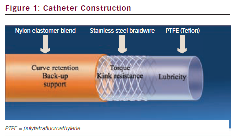
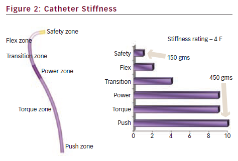
Guiding catheters are generally constructed of three layers (see Figure 1): a lubricious PTFE inner layer, a stainless steel braided layer and an outer soft nylon elastomer jacket. The stainless steel layer stiffens the catheter to provide support for device passage, but makes the guide more difficult to engage than a diagnostic catheter. ‘Thin wall’ guides have combined the outer two layers to achieve larger inner lumen diameters for any given outer diameter (French size) and are the predominant guiding catheters currently used. Guides have a shorter, more angulated tip and a larger internal diameter than similar diagnostic catheters.1 The larger internal diameter facilitates equipment delivery and contrast injection. The guide shaft has differential stiffness with the proximal segment being the stiffest with a transition to the most distal zone with a soft tip to prevent trauma to the artery (see Figure 2).
Guide catheter selection is based on vessel diameter, tortuosity, calcification, size of the ascending aorta, ostial orientation and planned complexity of intervention.2 In the US, guide catheters are available in diameter sizes from 5 to 8 F with each F being equivalent to 0.33 mm with inner lumen diameters (ILD) between 0.056–0.091 inch. The vast majority of interventions are performed with 6 and 7 F guides although with the use of the radial artery as an access site, 5 F guiding catheter use has recently increased. Most uncomplicated coronary interventions can be performed with a 6 F system. This will accommodate single stents and the use of two balloons if they are both rapid exchange. Bifurcation stenting can be performed with 6 F guiding catheters but requires staged stent deployment (modified ‘crush’ techniques). Two over-the-wire balloons will require a 7 F system and simultaneous two-vessel stenting mandates a large lumen 7 F guide with an ILD of 0.07–0.071 inch at a minimum but is often more easily performed through an 8 F system.3 Large lumen 6 F guiding catheters can accommodate up to a 1.75 mm rotational atherectomy catheters but larger French sizes are needed for larger burrs. Vessel characteristics including tortuosity and calcification may require the additional stiffness and support provided by a larger diameter guide. This additional stiffness raises the risk of trauma to the vessel. Additionally, larger calibre guides may cause vessel obstruction, as evidenced by dampening or ventricularisation of the pressure waveform, particularly in the presence of ostial disease. Dampening or ventricularisation indicates significant obstruction to flow, and/or a non-co-axial orientation of the tip. Proceeding may result in arrhythmia, haemodynamic compromise or dissection. Side holes at the catheter tip restore the normal pressure waveform but do not necessarily restore normal coronary artery blood flow, as effective blood flow through the side holes is limited.4 Contrast injection through the side holes may result in additional contrast utilisation and suboptimal coronary opacification.
The most commonly used guide shapes include the Judkins, Amplatz and Extra-back-up guides. Other proprietary shapes are provided by individual vendors for particular situations. The guide catheter should be selected in order to achieve co-axial engagement and the curve style should be selected on the basis of the size of the aorta, the angle of the coronary artery take-off from the aorta and the degree of support required for device delivery due to specific device or vessel characteristics.2 Dilated aortas require the use of larger sized curves (e.g. Judkins 5 instead of 4) especially for the left coronary artery. Variability in coronary anatomy will also necessitate changes in guide catheter strategy. For example, a JR4 guide will be unlikely to provide the required support for device advancement in a ‘shepherd’s crook’ right coronary artery (RCA). This will typically require an Amplatz or similarly shaped guide.
Vessel tortuosity, calcification and severe angulation also pose challenges for equipment delivery. Passive guide support is that provided by the guide design and buttressing of the guide against the opposite aortic wall. Active support refers to manipulation of the guide to conform to the aortic root. Additional support can be obtained by using extra-back-up guides, larger diameter guides or by deeply intubating the coronary artery with the guide. When working in the left coronary system, selective intubation of either the left anterior descending (LAD) artery or circumflex may be necessary to facilitate device delivery.5
For most routine coronary anatomy, the Judkins left or right, buttressing guides, such as EBU™ or XB™ guides are frequently utilised. For the LAD or an upward pointing LM, the XB LAD™ or Amplatz guides are often used. The upward pointing RCA is often best cannulated with a left internal mammary artery (LIMA) or Amplatz left guide and the downward pointing RCA often fits well with a multipurpose (MP) guide. The Judkins Right (JR), MP or right coronary bypass guides are useful for right saphenous vein bypass grafts and the left coronary bypass, hockey stick or Amplatz guides for left saphenous vein bypass grafts. The internal mammary artery can be cannulated with the LIMA or JR guides. Short 90 cm guides are available and useful when working on native coronary arteries through a bypass graft.
Guide Wires
A wide variety of guide wires are currently available for coronary interventions. Procedural success depends on both the ability to manipulate the guide wire to and past the coronary stenosis, as well as the wire’s capacity to serve as a rail for subsequent device delivery. The ideal guide wire is easily torqued and manipulated through the tortuous coronary artery, is atraumatic and yet provides adequate stiffness for the delivery of comparatively inflexible stents. Today, almost all wires are 0.014 inch in diameter. Most operators will select one all-purpose or ‘workhorse’ wire which will be used for most interventions. Wires that provide ‘extra support’, hydrophilic coatings and/or tapered tips are available for special situations such as vessel tortuosity, calcification and total occlusion, respectively.
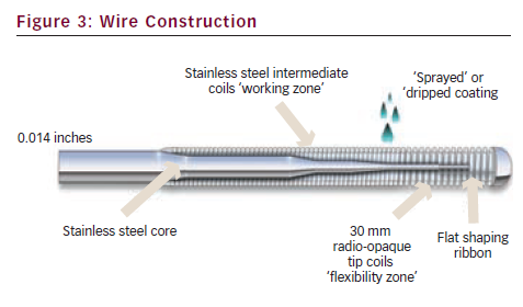
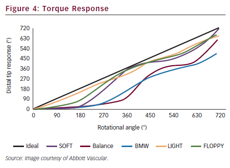
Guide wires are constructed with a central shaft of stainless steel or nitinol. The shaft tapers to a distal flexible tip spring coil made of platinum or tungsten (see Figure 3). Nitinol core wires are more resistant to kinking than stainless steel core wires but typically have less torque response. A variety of coatings are ‘sprayed’ or ‘dripped’ onto the wire to reduce friction. The tip strength varies from wire to wire, resulting in either stiffer or more floppy spring coil tips. The length of the core taper also changes the wire properties: if the core extends all the way to the distal tip, this results in a stiffer wire tip than a core that tapers rapidly before the tip, providing the former with a technical advantage for crossing chronic total occlusions. Hydrophilic polymer coated tips results in easier passage through highly stenotic lesions and tortuous anatomy by reducing friction. This advantage, however, comes at the expense of an increased risk of wire perforation and dissection. Torque response is an important feature of guide wires and refers to the transmission of rotation from operator to wire tip. One-to-one torque response is desirable and this feature is one of the most important in physician decision-making for wire selection (see Figure 4). Core to tip construction improves torque control. Specific taper designs also influence torque response.
Difficulties in device delivery are not unusual in tortuous, angulated and calcified vessels. Starting with an ‘extra support’ wire, or exchanging the ‘workhorse’ wire for same may also be helpful in this situation as the added stiffness of the support wire may allow device delivery where the ‘workhorse’ wire could not. However, extra support wires are less likely to conform to the vessel’s path and may result in wire bias that further hinders device delivery. Also, advancement of a second wire (‘buddy wire’) may aid in straightening tortuous segments and facilitate equipment delivery.6 Both of these techniques may significantly straighten out a previously highly angulated coronary causing so-called ‘pseudo-lesions’ to develop.3 These should not be mistaken for true stenoses and withdrawal of the wire proximal to the tortuous segment will confirm that these are not true lesions once the natural vessel angulation is restored.
Guide wire complications are less common in the contemporary era due to advances in wire design although they do still occur. Meticulous operator technique and attention can reduce these further. The most common complications are perforation and dissection. Perforations tend to occur most commonly when aggressively attempting to cross a chronic total occlusion or when the distal tip of a hydrophilic wire migrates into a very small branch.2
Dilation Catheters – Balloons
Although now rarely used as stand-alone devices, balloon catheters are commonly used in pre-dilation of lesions before stenting and post-dilation to achieve optimal stent expansion. However, balloons are still used alone in the angioplasty of small vessels, rescue of bifurcation side branches following parent vessel stenting, in in-stent restenotic lesions and in situations where stent delivery proves impossible.2
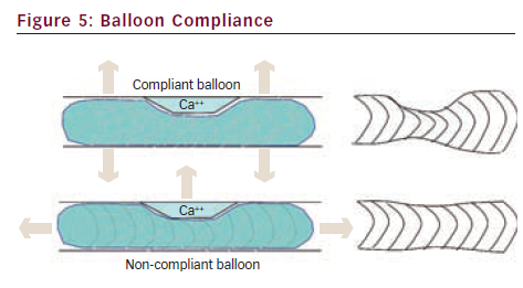
There are several characteristics of balloon catheters that define their clinical utility. Compliance is a measure of balloon ‘stretchability’. It is defined as the change in balloon diameter per atmosphere of inflation pressure. The physical characteristics of the balloon material determine the compliance, with compliant balloons typically constructed of polyolefin copolymer and non-compliant balloon material being composed of polyethylene terephthalate.1 Compliant balloons are typically more deliverable than non-compliant balloons due to a lower profile and greater flexibility. Knowledge of balloon compliance is critical for safe and effective angioplasty, as compliant balloons expand in both diameter (‘dog-boning’) and length significantly with high inflation pressures.2 Thus a non-yielding stenosis dilated with high pressures using a compliant balloon may result in significant vessel injury in the arterial segments adjacent to the stenosis due to balloon-vessel size mismatch (see Figure 5). Non-compliant and semi-compliant balloons expand much less and retain their stated diameter with higher inflation pressures. This confers an advantage in dilating rigid lesions and for post-dilating stents. However, non-compliant balloons do not re-wrap very well and, thus, can be difficult to re-use after initial inflations.
Awareness of an individual balloon’s compliance and inflation characteristics is critical in performing safe vessel dilation. All balloon catheters are supplied with in vitro derived pressure ratings. The nominal pressure is the minimum pressure required to achieve the specified balloon diameter. The rated burst pressure (RBP) is the pressure rating below which 99.9 % of balloons will not rupture. Mean burst pressure is not usually supplied by the manufacturer but is the pressure at which 50 % of balloons will rupture. It is invariably higher than the RBP.7
Balloon profile refers to the diameter of the deflated balloon and distal catheter shaft. Historically, large differences in catheter profile translated into marked differences in ease of deliverability when catheters were compared. Measurable differences in balloon profile still exist, however, virtually all balloon catheters used in today’s catheterisation laboratories are extremely low-profile devices.2 Trackability refers to the balloon’s ability to track the wire up to the target lesion while pushability refers to the ability to cross the lesion with the balloon. These are not easily measured in vitro but are perhaps more important than catheter profile in today’s practice of interventional cardiology.7
Balloon catheters are either over-the-wire (OTW) or rapid-exchange (RX). Most OTW and monorail balloons are compatible with 0.014 inch guide wires. OTW balloons require use of exchange length 300 cm wires. Using an OTW system, the guide wire can be advanced to the stenotic region either through the balloon or ‘bare’. Advantages of an OTW system include the ability to bring the balloon catheter closer to the wire tip to enhance support in crossing very tight stenoses, as well as using the balloon to increase wire torque transmission in tortuous vessels. OTW balloons allow for wire exchange beyond a stenosis. Additionally, OTW balloons allow intra-luminal position confirmation. In an RX system, only the distal portion of the balloon has a guide wire lumen and tracks over the wire. RX balloons therefore have a lower profile and permit the use of standard length 180 cm guide wires. Because of the short portion of the catheter that tracks the guide wire, RX balloons tend to have less pushability and trackability than OTW systems. The ‘hypotube’ used in RX balloons to transmit forward push also adds slightly greater stiffness than OTW products which can cause difficulties in delivery or ‘backing out’ of the guiding catheter in situations of vessel tortuousity and/or calcification.
If balloon angioplasty alone is planned as the sole revascularisation strategy, a balloon:artery ratio of 1.1:1 has been suggested as optimal.8 The balloon length should be 2 mm longer on either end of the lesion and a compliant balloon should be attempted first with non-compliant balloons reserved for the lesion that fails to yield. Longer durations of inflation should be considered as well. If stenting is planned, a balloon: artery ratio of 0.75–1.0:1 is suggested, with the balloon length being shorter than the intended stent length, in order to minimise intimal injury or dissection beyond the stent margins. Shorter durations of inflation are required with stenting than balloon angioplasty alone.
Conclusion
A thorough knowledge of the basic angioplasty equipment is required for coronary intervention. The correct choice of equipment can make a complex intervention appear effortless, whereas the less appropriate equipment choices can make a straightforward intervention, laborious and challenging.