


As the role of percutaneous coronary intervention (PCI) has evolved, inevitably, so too has the technology associated with this specialty. Initially, plain old balloon angioplasty (POBA) was developed as a strategy to ‘stretch’ focal stenoses within the coronary arteries leading to a relief from ischaemia and angina. Whilst potentially of great benefit to some patients, POBA was beset by a series of Achilles’ heels. These included early, unpredictable and abrupt vessel closure due to coronary dissection, subacute recoil of the dilated coronary lesion with the stenosis recurring relatively early, and later restenosis due to the healing response invoked by vascular injury from the procedure. Ultimately, supplementary technologies were needed to resolve these issues and this led to the concept of deploying bare metal stents (BMS) in the coronary artery. Early BMS were developed to more reliably treat short, focal areas of disease. The aim of using these devices was to cover disruption and stabilise dissection associated with POBA, thus preventing abrupt vessel closure. In addition, the vessel was scaffolded to prevent early recoil and the initial results from widespread adoption of coronary intervention with BMS led to benefits for patients.1 One feature of early BMS was that they were relatively bulky and stiff devices. This reflected their initial function for the treatment of focal and straightforward coronary lesions. As the practice of interventional cardiology evolved to meet the needs of patients with more complex coronary lesions, so too did the stents. There was an explosion of different manufacturers, stent designs and technologies.2 Therefore, early platforms quickly improved, becoming easier to deliver and thus more user-friendly. Whilst the majority of these devices were constructed from stainless steel, there was a range of stent cell construction (open versus closed), cell geometry, strut thickness and different materials were also explored (such as gold, carbon and a variety of others).
However, it soon became clear that BMS were beset by the late complication of in-stent restenosis (ISR). This late ‘healing phenomenon’ led to loss of the treated vessel lumen and a recurrence of ischaemia. Repeat procedures (target lesion revascularisation [TLR] and target vessel revascularisation [TVR]) became a frequent occurrence after PCI with BMS. It also became apparent that ISR was associated with many of the design features of these devices. These included longer stent length, smaller stent diameter, a high metal:artery ratio and strut thickness.3–5 Clinical features such as the presence of diabetes also contributed to stent failure.3 There were both early and long-term adverse consequences of ISR for patients.6,7 These events also led to a clinical disadvantage for patients with multivessel disease who were treated by PCI compared with those who were offered coronary artery bypass grafting (CABG).8,9
Ultimately, this brought about the development of drug-eluting stents (DES). These devices were first introduced in the pivotal Randomized Study with the Sirolimus-Coated Bx Velocity Balloon- Expandable Stent in the Treatment of Patients with de Novo Native Coronary Artery Lesions (RAVEL) trial.10 DES had polymers and a variety of different drugs coated onto stents to stop late lumen loss. The therapeutic goal was to reduce the inflammatory and healing response that occurred after stent implantation, with the aim of preventing ISR and its clinical consequences. DES were very effective in reducing levels of ISR relative to BMS and their use quickly became widespread. However, their introduction and dissemination meant that the original design concepts that applied BMS now also needed to facilitate timed and consistent drug delivery. By this time, the design goals that previously applied to stent manufacture had been expanded and significantly altered. Investigations of different drugs, polymers and their combinations became prominent and essentially superseded platform design as manufacturers sought to produce increasingly safe and effective devices.
One significant effect of DES was that patients with a previously difficult disease, such as those with diabetes or multivessel disease, could be treated.11,12 As a result, more and more challenging lesions became amenable to PCI. In addition, stent design was also pushed forwards by operator feedback that led manufacturers to encompass potentially desirable properties in their products. These included improved radiographic visibility, flexibility, device deliverability and conformity to the vessel. In general, the overall trend in design goals was to produce thinner stents that are more flexible but where the key mechanical property of the stent (the radial strength and hence the scaffold within the vessel) has been preserved.
Stent platform design and manufacture has now come back under the clinical spotlight for a variety of reasons. These include the expanding use of these devices in previously ‘taboo’ clinical areas (bifurcations, chronic total occlusions, left main disease) with an increasingly complex demand placed on their mechanical performance. It has become apparent that these properties are paramount not only with regard to the mechanical properties of the stents but also to clinical outcomes in these challenging clinical scenarios.
Stent Materials, Design, Longitudinal Strength and Stent Fracture
Metallic stents are manufactured by different processes. These include laser cut slotted tubes, multilink hoops and the sinusoidal continuous wire, which is a single unit that is wound, folded and welded into shape. The stent must apply sufficient radial force on the wall of the diseased coronary artery so that the vessel lumen is restored to a near normal diameter whilst subsequently scaffolding the vessel and preventing collapse of the artery in the longer term. Desirable performance characteristics include low elastic recoil, conformability, high visibility and ease of deliverability. The latter is a complex parameter influenced by the flexibility afforded by the stent itself, the properties of the delivery balloon system and the overall crossing profile of the entire device.
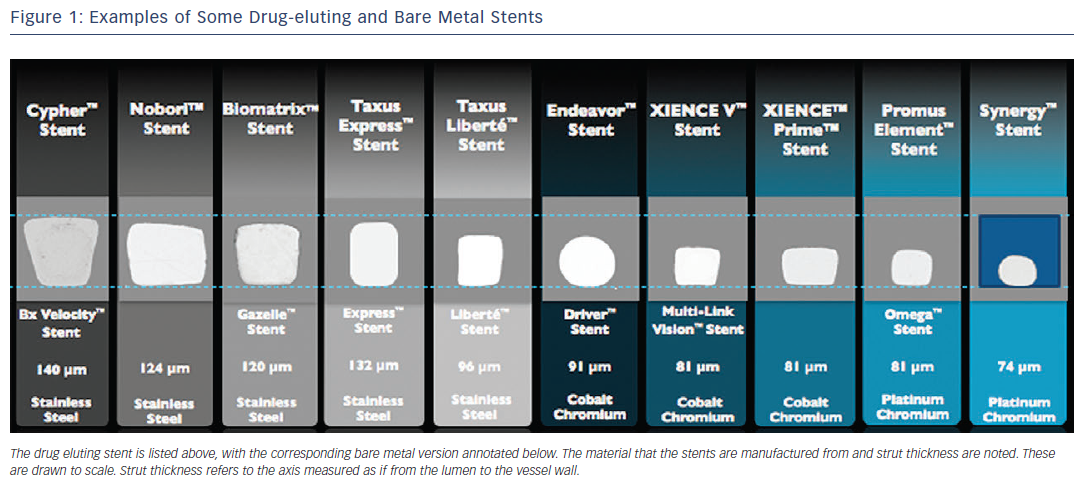
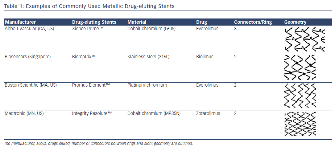
Mechanical engineering is a science of compromise. Therefore, altering any single feature of a stent inevitably affects other properties. There is a complex interaction between every feature of stent design and how the device behaves in clinical practice.13The radio-opacity of a stent is mainly dictated by the material (usually a metallic alloy) from which it is constructed, where the resistance to penetration by X-ray is proportional to the cube of the atomic number of the elements that make up the alloy.13 There are a range of metallic alloys that are employed in commonly used stents. These include stents that are constructed from 316L stainless steel, cobalt chromium alloys (MP35N and L605) and platinum chromium alloys (see Figure 1 and Table 1 for examples). The alloy that the stent is constructed from will not only alter the radio-opacity but also the elastic modulus (a material’s tendency to be deformed elastically or non-permanently when a force is applied to it), yield strength (the stress at which a material exhibits plastic or permanent deformation) and tensile strength (the maximum stress that a material can withstand whilst stretched or pulled before its cross-sectional area significantly contracts).14 In clinical terms, these latter features dictate the overall radial strength of the stent itself, in addition to its susceptibility to recoil. These two features are not mutually exclusive. However, these properties are crucial for both the acute and long-term performance of the stent. The evolution away from stainless steel towards other alloys has been to allow the stent struts to become thinner whilst maintaining the overall radial strength of the device.
Most recently, bioresorbable stents have been introduced to the clinical arena. The most extensively studied stent is currently the Absorb™ (Abbott Vascular, Santa Clara, CA, US). This stent is manufactured from a poly-L-lactic acid (PLLA) polymer. This semi-crystalline polymer is constructed from a number of linked sinusoidal hoops with stent struts that are 150 μm thick.15 This particular stent cannot be seen radiographically and has two small metallic markers sited at the distal and proximal stent edges for intra-procedural identification. A number of other bioresorbable materials and platforms are under investigation at various stages,15 although a review of these materials and devices is beyond the scope of this article. Nevertheless, the same mechanical constraints and desirable properties are also directly applicable to these devices.
A major factor in stent design is the geometry of the stent cell structure (see Table 1). This is dictated by the number and pattern of connectors between rings or hoops. Reducing the number of fixed connectors is potentially desirable as this improves flexibility, delivery and decreases the metal:artery ratio. However, this also potentially impacts negatively on longitudinal strength. It has recently become apparent that longer, thinner and more flexible stents can be less stable in their longitudinal axis. These stents can be ‘compressed’ or distorted along the length of the device creating a ‘concertina’ effect or longitudinal stent deformation (LSD).16,17 This phenomenon is now well-understood and usually relates to an interaction between guiding catheters and stents deployed in the aorto-ostial position, or stents that are relatively undersized after initial deployment that are subsequently ‘caught’ and distorted by secondary equipment that is passed into the coronary vessel.14,16
With regard to longitudinal stability, there are several technical design factors that are associated with an increased susceptibility to LSD. It has been shown that at compressive forces of 50 gF (0.5 N) or less, it is possible to shorten18 or elongate19 modern metallic stents. Stent alloy and strut thickness appear to be somewhat less important with regard to susceptibility to LSD. The construction of the device, number of connectors between rings and their geometrical distribution across the device dictate the longitudinal strength of the platform. In general, more connectors between rings correlate with increasing longitudinal strength. Where connectors are present, those that are in longitudinal alignment confer increasing strength, whilst offset connectors are less strong. However, there is a significant downside to increasing the longitudinal strength of the device. This will increase the ‘stiffness’ of the stent, therefore reducing its deliverability to and conformability within the vessel.
Whilst unrecognised, LSD has the potential to be clinically disastrous for the patient. However, these events appear to be relatively rare.
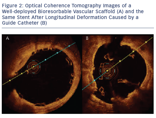
Where LSD does occur, a three-pronged approach is required to manage the stent deformation. Ideally, preventative measures should be undertaken, such as prudent guide catheter selection in ostial lesions to allow for sufficient support without excessive guide engagement. Choosing a stent of an appropriate size and careful proximal stent optimisation (usually with softer semi-compliant balloons in our practice), particularly in the left main stem, will help to ensure that secondary devices are unlikely to catch on struts and cause deformation. Secondly, a low threshold is required for suspecting stent deformation, particularly when there is resistance in delivering post-dilation balloons. Careful fluoroscopy examination and or additional imaging with intravascular ultrasound (IVUS)/optical coherence tomography (OCT) may be necessary to diagnose this problem.16 Finally, if longitudinal stent compression has occurred, cautious post-dilation should be attempted. Small diameter balloons may initially be required to cross the damaged stent, and these can be gradually upsized as necessary. This method has been used with success in our experience.16 Further proximal stent deployment may be needed in the setting of vessel damage.14,16 It is worth noting that this phenomenon can also occur with bioresorbable platforms (see Figure 2). Should this occur, OCT will be necessary to demonstrate the complication.
Nevertheless, there is a clear trade-off with increasing the stiffness of a stent. Whilst longitudinal stability rises with the number of stent connectors, the risk of stent fracture increases as the stent becomes stiffer. Therefore, older stent platforms are much more susceptible to this phenomenon. In one clinical study, the 6-connector Cypher stent was more than four-times more likely to fracture than newer platforms.20 The incidence of stent fracture with the Nobori™ 2-connector Biolimus eluting stent (Terumo Corporation, Tokyo, Japan) is reported at >4 % per lesion at nine-month angiographic assessment in a study of >1,000 patients.21 This may relate to the exact shape of the connector between rings for this particular stent. Fracture has also been described in the thinner strut, 3-connector Xience™ stents (Abbott Vascular, Santa Clara, CA, US) where a combination of LSD and stent fracture were also associated with adverse clinical events.22 This was particularly likely to occur at areas of stent overlap. Another study has suggested an incidence of stent fracture in Xience stents at almost 3 % in a large cohort of >1,000 patients undergoing follow-up angiography between 6 and 9 months.23 Stent fracture is likely to lead to ISR, acute or chronic occlusion and is certainly not a benign phenomenon. 20–23 These events are predisposed by certain features within the lesion or vessel. These include treating the right coronary artery, using longer stents, areas of tortuosity, calcification, stent malapposition and stenting at hinge points.
Therefore, whilst LSD can occur as a sudden and dramatic event that complicates a PCI, this can usually be managed and resolved provided that it is recognised. Our experience is that patients do well over the long term when this is the case. In contrast, stent fracture is much more difficult to predict and it also seems to be a more common phenomenon than was previously considered to be the case. Furthermore, there is a high chance of an adverse outcome with stent fracture. Whilst LSD is certainly not desirable, the trade-off of a more flexible and conformable stent platform with less axial stability may be worthwhile if these platforms prevent later complications that are likely to occur in significant numbers. This is becoming increasingly relevant in the era of treating long segments of disease with stents that can be as long as 48 mm and the frequent need for overlapping stents (as is common when treating chronic total occlusions). Newer approaches have been adopted more recently. For example, the Promus Premier™ and Synergy™ II stent models (Boston Scientific, Natick, MA, US) aim to retain flexibility through the body of the stent by using two offset connectors. However, the most proximal three rings are linked by extra connectors to provide resistance to LSD.
Stent Models Across a Product Range, Bifurcations and Over-expansion
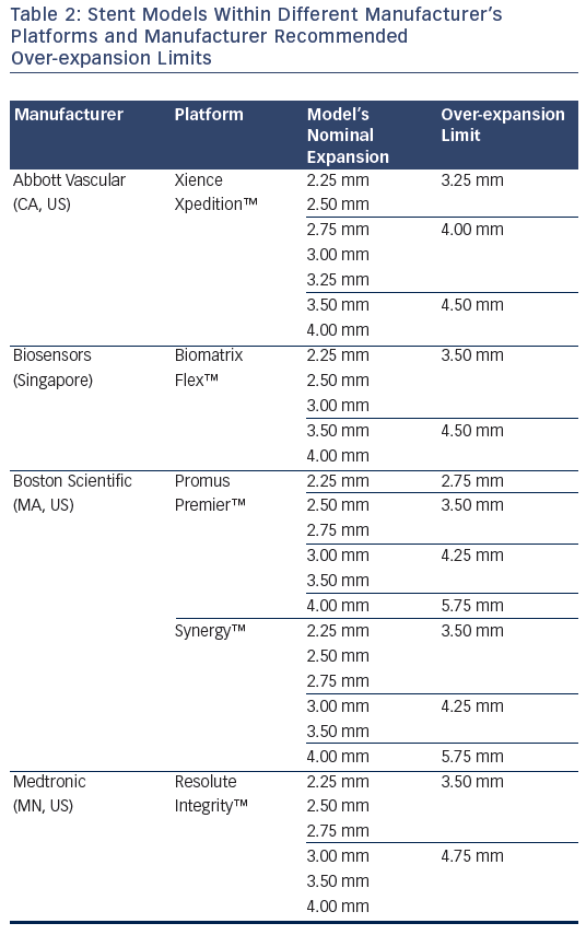
It is imperative that cardiologists are intimately familiar with the stents that they use. A differing range of stents occur within the various manufacturer product ranges (see Table 2). Understanding the differences between the stents within these product ranges is key to obtaining a good clinical outcome for the patient. This is becoming more important as the lesion complexity increases. For example, using a two-stent strategy at a bifurcation could potentially have a vastly different mechanical result depending on which product is chosen. If a 2.5 mm diameter product is brought from a side branch back into a much larger diameter main vessel, the final expansion in the proximal main vessel and stent cell diameter (and thus lumen achieved in the main vessel) will be very different than if a 3 mm or 4 mm version of the ‘same stent’ is deployed in the side branch instead. Understanding the implications of these choices is crucial. This is particularly pertinent when the left main stem (LMS) is being treated.
With LMS intervention, over-expansion of current stent platforms is frequently required as the devices are brought back from smaller diameter daughter vessels (LAD or left circumflex). Despite bench testing demonstrating that current drug-eluting stent platforms can maintain structural integrity beyond the nominal expansion diameter,24 there are theoretical concerns that over-expansion may affect drug delivery and cause mechanical disruption of the stent.
The first concern regarding over-expansion is that it may damage the stent polymer, leading to uneven drug elution, with a potential for later ISR.25 Bench testing of over-expansion of first generation DES found that balloon dilation induced only minor polymer coating abnormalities, which have also been noted on undeployed DES.26,27 It is also possible to replicate this polymer damage by delivering stents through tortuous and calcified vessels. Another concern with respect to over-expansion is the risk of mechanical disruption of the stent. Stent fracture is possible with overly aggressive stent expansion.
A further mechanical issue with over-expansion that has been queried is of the potential for stent recoil. This is a theoretical concern due to a reduction in metal:artery ratio and an alteration of the scaffold itself. Stent recoil has been described when treating atheromatous vessels.28 However, in the LMS the usual reason for over-expansion is apposition to the non- diseased vessel wall rather than scaffolding flow limiting plaque. Furthermore, the radial strength of the stent paradoxically increases as it is over-expanded. This is due to straightening of both the ring and connectors, thus leading to greater strength, not less.
Our experience of LMS PCI is that this is typically a very large vessel. In a study of 125 patients, the mean cross-sectional area of the distal LMS was 22.6 mm2 (standard deviation [SD] ± 5.4 mm2) and mean maximal vessel diameter was 5.7 mm (SD ± 0.7 mm).29 Therefore, the vast majority of patients would consequently require post-dilation beyond the nominal diameter of all of the large vessel platforms of current generation DES during LMS PCI. We also performed a further prospective clinical study where all patients who underwent IVUS-guided LMS PCI and stent post-dilation beyond suggested expansion limits were entered into a registry. In 31 patients, mean maximal stent diameters of >5.0 mm were reliably achieved (using Biomatrix Flex™ 9 crown and Promus Element Large vessel platforms) with 5.5 mm and 6.0 mm post-dilation balloons. No intra-procedural complications occurred and in 13.4 months of follow-up only one patient experienced clinical ISR.29 This indicates excellent short-term efficacy and no increased complication rate with over-expansion of current generation DES in the LMS. These results compliment the bench data of Foin et al., but in the clinical arena.24 It should be noted that under-expansion or incomplete stent apposition of BMS or DES is strongly associated with ISR and stent thrombosis.30–32 We would suggest that leaving undersized and unapposed or malapposed stents in the LMS should be avoided at all costs.
Conclusions and Future Directions
The evolution of the role of stents has resulted in a significant change in stent design, primarily driven by the requirements of the disease that is being treated. Stent design is crucial for acute and long-term outcomes for patients and it is critical that cardiologists have a complete understanding of the design features of the devices that they are implanting.
It is likely that LMS PCI and the treatment of large vessel bifurcations will become a mainstream application of PCI over the forthcoming years. Manufacturers may need to consider producing dedicated platforms for the treatment of these vessels. As more patients with multivessel disease are treated greater attention will also need to be placed on longer-term outcomes in more demanding clinical settings. The risks of latent stent fracture may assume a more prominent role in clinical studies in future. Ultimately, as the clinical practice of PCI continues to evolve, manufacturers and clinicians will have to work closely in partnership to make sure that the devices that are implanted can provide excellent safety and long-term efficacy for patients. The importance of stent design has been re-emphasised and is likely to become increasingly relevant in future, where the patient and lesion being treated are likely to mandate very careful selection of the stents that are deployed in each individual setting. The focus should be shifted away from producing ever more deliverable stent platforms and should be moved back to the fundamental properties of what the device has been built to achieve.